*This article, by Arnold Van Acker (†) & Stef Maas, was originally published in CPI 2-2021.
AN OVERVIEW BASED ON PATENT RESEARCH
The idea to reduce the self-weight of concrete slabs by putting voids in the centre of the cross-section, dates to the beginning of the previous century. Several inventors from different countries applied for patents on various systems. The present article is mainly based on an analysis of patents published during the first half of the 20th century, and personal experiences from 1960 on. Patents usually offer a complex description of inventions (claims). Reconstructing the history of hollow core slabs based on these patents is a laborious but fascinating exercise. This article aims to give a general overview and is not meant to be exhaustive.
It is not always clear how to make a distinction between ‘real’ hollow core elements and similar types of decks such as box decks, bubble decks, I-shaped small beams placed side by side, etc. The European Product Standard EN 1168 [1] defines a hollow core slab as a monolithic prestressed or reinforced element with a constant overall depth divided into an upper and a lower flange, linked by vertical webs, so constituting cores as longitudinal voids the cross-section of which is constant and presents one vertical symmetrical axis (Fig. 1). The present article deals with hollow core slabs according to the definition of EN 1168 only.
Systems
Based on the patent applications, we can distinguish 3 main systems of hollow core slab manufacturing. For each category subcategories can be defined:
1. Wet cast
1.1. Permanent void formers
1.2. Temporary void formers
2. Slip forming
2.1. Tamping
2.2. Vibrating
3. Extrusion
3.1. Compaction by high frequency vibration
3.2. Shear compaction
In general, these manufacturing methods can be used for the production of reinforced slabs as well as for the production of pre-stressed slabs. They are mostly in normal dense concrete, but there are also examples of structural light weight concrete.
In the early days, hollow core slabs were manufactured eitherin a plant, or on site. Often individual moulds were used and sometimes even long line beds, but in a discontinuous way. The compaction of the concrete was mostly carried out by tamping the fresh concrete. Here also a patent study could bring more insight, but it is not the main subject of the present article.

Specific characteristics of hollow core slabs
The most characteristic feature in the development of hollow core slabs was that they deviated strongly from the at that time existing design principles of reinforced and prestressed concrete, by which compression is taken up by concrete and tension by reinforcement. Indeed, in most cases, the developed manufacturing technique was only possible under the following conditions:
- No vertical web reinforcement;
- No transversal reinforcement at the bottom side
of the units; - Only longitudinal reinforcing bars or prestressing
tendons; - No protruding reinforcement for connections, etc.
As a consequence, the tensile capacity of the concrete had to be taken into account in the design and new techniques for connections had to be developed. This was new especially with regard to transfer of forces at the support, shear capacity of the units, diaphragm action of the floors, transversal load distribution among adjacent units, non-rigid supports, floor openings, fire resistance, etc.
With regard to prestressed hollow core slabs, the fib Commission on Prefabrication played a crucial role in the development of the design. Extensive research and intensive field experience gathered from all over the world, learned that hollow core floors are perfectly able to fulfil all the needed structural functions, on condition that some elementary design principles are met. In 1988 the FIP Commission on Prefabrication published Recommendations for the design of prestressed hollow core floors. They have been used as a basis for national and international standards, for example the Eurocode 2 and the European CEN Product Standard EN 1168. An updated version of the FIB Recommendations 1988 will be published this year.
Historical developments
Today’s prestressed and reinforced hollow core floor slabs are the result of a long period of development and testing. New variants of the hollow core slab are still finding their way to the market (see for example the transversely curved hollow core slabs for the tunnel vault on the Italian A4 autostrada at the entrance of the trade fair area in Milan [2]). Even more than the hollow core slab itself, the production methods are subject to permanent optimization.
In the following, the historical developments are classified according to the above mentioned three production systems.
Wetcast
The wet cast technique is using preformed cores (void formers) to realize the longitudinal voids. They are positioned in the mould prior to the casting of the slab.
Wet cast with permanent void formers
Wilhelm Siegler (Germany, 1906) can probably claim the first application of longitudinal void formers in concrete slabs [3]. His system to realize cores was based on prefabricated short moulding tubes in hardened mortar or another material, which were positioned on a scaffolding (Fig. 2). The length of the slabs was arbitrary. The tubes had lateral lugs at the bottom, serving as mould for the webs. They were placed either continuously in the longitudinal direction, or with short inter-distances at certain places to form transversal ribs. The longitudinal and transversal webs were reinforced in the classical way.
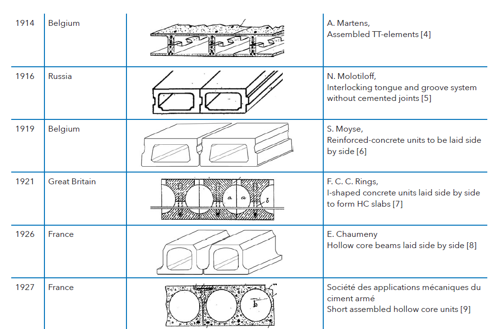
During the following two decades several solutions to form longitudinal voids in flat floor slabs were developed. An overview is presented in Table 1.


The question could be raised about the distinction between hollow core elements and box elements. The above variants still correspond to the definition of hollow core slabs given afore, but from a certain thickness on, they are to be classified as box slabs or beams. By the way, the inventors of the solutions of Table 1 are in the first place claiming for floor slabs, although they do not exclude in the patent description the applicability for box beams or even walls.
Today, this production technique is rather rare but is still used. After pouring a bottom layer, prismatic void formers, usually in polystyrene, are installed. Afterwards, a second layer of concrete is poured to shape the webs and the top layer.
Wet cast with temporary void formers
In 1930, a patent is granted to the Belgian inventor Jules Heyneman for a precast floor slab with longitudinal voids [10]. These voids are formed by means of elastic moulds made of e.g. steel and held in place by wedges. When these wedges are removed, the cross-section of this mould is reduced, and the mould can be removed from the hollows in the beam without difficulty. Unfortunately, the drawings of the patent contain no details about these void formers. The number of voids in the cross-section could be modified. The floor units were in reinforced concrete. The patent describes mainly the product itself, without any detail about the manufacturing. The longitudinal joints between the units are indented and provided with transversal reinforcing stirrups. They were filled on site with mortar.

The inconvenience of the solution was of course the weakness of the flexible steel pipes. In 1939 a solution with pneumatic expansible and collapsible rubber core forms was patented by Walter H. Cobi (US) [11]. Fig. 4 shows a longitudinal
and transversal section of the system.

Afterwards several variant solutions were patented with respect to both the shape and the number of cores and the profile of the longitudinal joints.
Charles Lethbridge (GB) [12] presented in 1940 an improved method with removable steel tubes of uniform cross-section extending longitudinally through the whole mould and conforming in shape to the cross-sectional form of the hollow core unit. After positioning of the desired reinforcement bars, the concrete was cast, and the mould vibrated as a whole. At the same time the core tubes were slightly moved relatively to the mould. When the concrete was sufficiently compacted to maintain its shape, the tubes were withdrawn via the end of the mould and the concrete was left to harden. By the employment of metal core members with a smooth surface and maintaining them in motion, the concrete was prevented from adhering to the tubes and the latter could be removed without difficulty. Preferably and for simplicity the core tubes were of circular cross-section which allowed for a rotary motion during casting.
In France in 1952, STUP Freyssinet [13] applied for a patent for the manufacture of prestressed hollow core elements on long steel beds. The invention was meant for floors of buildings. The units were in prestressed concrete, with a length equal to the floor span without intermediate supports, and a variable width in function of the needed slab thickness and the possibilities of handling. The elements had longitudinal voids over the whole length, with a circular shape. The vertical edges were profiled and filled with mortar after erection, to enable the transmission of vertical loads from one element to the others. The elements were cast on long line steel moulds. Transversal mould plates could be placed at any place to realise the length of the units. The longitudinal voids were moulded with long tubes in reinforced rubber, inflated with a liquid under pressure before and during casting. After compaction of the concrete, the pressure was released, and the tubes removed.

Slip forming
The slip form technique is characterized by a moving profiled mould (form) into which the concrete is poured and compacted. In general, a higher slump concrete is used.
Slip forming (tamping)
In March 1931, the German Wilhelm Schäfer [14] applied for a patent to make precast reinforced and prestressed hollow core slabs on long line beds in stacks one line above the other. His purpose was to improve an already at that time existing production system (patent not available) based on a kind of slip form technique with movable cores and side plates, in which the different production steps were executed one after the other. His patent describes how to make the production in an automatic continuous way. We could consider it as a precursor of the slip form system. Patents were granted in Germany, in UK, in the USA and in Switzerland, all in 1933.
The casting machine was hanging in a movable frame and comprised short follower tubes for the realization of the voids plus edge moulds. All operations (e.g., filling the mould, tamping the concrete, producing the voids, and removing the lateral plate edges) were done for the entire bed length automatically and without interruption. The machine comprised also a device to smoothen the top surface of the slab. Then a sheet of paper was put on the finished line, the machine lifted to a higher position and the casting operation repeated for the next line on top of the previous one.
The concrete is compacted in these machines by means of fingers that tamp the concrete. Consequently, we call this we this method of slip forming ‘tamping’.

The American company Spancrete purchased the Schäfer patent and started around 1950 the production technique of prestressed hollow core elements, in which a series of long lines were cast in stacks, each line on top of each other. Once the upper slab of a pile had hardened, a diamond disk sawing machine was mounted on that pile of slabs, and hollow core units were cut and removed.
Wilhelm Schäfer got in 1951 a patent for long span prestressed hollow core floors [15]. The elements had a particular longitudinal edge profile containing a dovetail groove and could be manufactured with a thermal insulation layer at the soffit. The manufacturing technique is not mentioned in the patent, but we presume that it concerns the same slip form technique as described above.

Slip forming (vibrating)
The most common way to compact concrete during slip forming is by means of vibrations.
In 1952, a patent was granted to the Wacker Brothers (GE) [16]. Inspired by a patent from 1938, describing a method and apparatus for manufacturing pipelines, this company developed a method to shape and compact concrete in moving moulds. The compaction is realised by vibrating the concrete. In 1953, Max Gessner of Locham (Munich, GE) applied for a patent [17] dealing with compaction equipment to produce prestressed beams or structural elements made of reinforced concrete. This patent, granted in 1957, presents the use of a vibrating slip form machine on a single casting bed which is the most common configuration these days.
Gessner’s ideas were further developed by the West German companies Max Roth KG and Weiler KG.
In 1957, Weiler GmbH (GE) applied for a patent for a slip form moulding machine invented by Hans Geiger [18]. Geiger was also inspired by the Wacker Brothers and developed a manufacturing method for prestressed single and double-T beams. The method was also applicable for hollow core elements.
The machine comprised two parts connected to each other, each having a hopper, vibrating plates and levelling plates. The casting was done in two steps: in the first step, the lower part of the unit was cast, compacted and levelled;
in the second step the upper part was cast in a similar way. The machine presented by Geiger is very similar to slipform machines existing today. Weiler developed the machine further for their production of prestressed hollow core slabs and commercialised the complete manufacture including machinery and casting beds. Weiler GmbH is these days known as Maxtruder GmbH.
Also Max Roth from Germany developed around that period a slip form machine for prestressed hollow core slabs. In 1962 the company applied for a patent [19] (granted in 1965). The company already developed a slip former in the mid 50’s for the manufacturing of T- and L-beams. This patent documents a slip former in which the concrete is poured and compacted in three layers. Later, other companies (Spiroll Corp Ltd, SpanDeck inc., VBI Development, Elematic Oy AB,..) would also refer to this patent in their patent applications.

The company Echo in Belgium started in 1963 the production of prestressed hollow core slabs with a Roth machine. After a short period of experimentation, Echo developed its own production machinery. In 1990 this activity led to an independent subsidiary Echo Engineering. Echo Engineering now belongs to the Progress Group and is called Echo Precast Engineering.
In 1965 David Dodd got a US patent for a slip form machine with only one hopper, in which the entire slab was cast in one step [20]. He described it as a self-propelled extrusion type slip forming machine, suitable for use with relatively dry concrete mixes.

Another variant method of the classical slip form machine concerns the Tensyland flow former machine with only one hopper [21]. The flow former uses only the self-weight of a concrete column inside the casting machine in combination with the vibration required to settle the aggregates so that the concrete flows through a static mould.
Slip formers have been used to cast hollow core slabs with depths far beyond the scope of the standard EN 1168. The Italian company Nordimpianti, specialized in the construction of slip form machinery since 1974, commercialises machines capable of producing elements with a height of 1 metre. This category of elements is not part of the scope of this article.
Extrusion
With the extrusion technique, a very low slump concrete is pressed by means of screws (augers) into a moulding compartment that shapes the concrete into the required cross-section. The concrete is compacted by vibration in combination with pressure. The pressure caused by the augers results in the forward movement of the extruder.
In 1912 already, the Italian inventor Achille Gaiba introduced a patent for his machine to produce continuous reinforced products, in which the shaping and compaction of the product was realised only by pressure of a plastic concrete mix into a moulding compartment, without further vibration [22]. He refers clearly to the manufacture of water pipes, but the patent is not limited to pipes alone.

The fresh concrete introduced by the hopper was pushed by a multi-bladed propeller towards the opening and further to the moulding compartment. In this way the concrete was subjected to a high pressure and filled the mould without further vibration.
Another application of concrete compaction by pressure without vibration was by John Murray US in 1928 [23]. The method and apparatus could be used for forming continuous conduits, in which plastic concrete was forced by pressure into a progressively movable mould. His invention was specifically aiming at the realisation of underground conduits, having a plurality of ducts for carrying electric cables. 40 years later, Glenn Booth from Spiroll Corporation was referring to this document in his patent of 1966 [25].

Extrusion with high frequency vibrators
In July 1961, a patent was granted in Canada to Ellis and Thorsteinson, for a Machine for extruding hollow cored concrete sections [24]. The patent describes an extruder. The extruder was presented as an improvement of the most used
processes at that time, being moulds with inflatable cores.
The method specifies the forming of longitudinally cored concrete slabs upon an extending pallet by squeezing the concrete trough a moulding section by means of an auger. The concrete is compacted by means of a vibrator on top of the moulding section.
Around the same period, another Canadian company Dy-Core developed also an extrusion machine.
In his patent of 1965 [25], Glen Booth, Spiroll Corporation Canada, applies for several improvements of the devices described in the patent of 1961 [24]. Specifically, it concerns the inclusion of a separate vibrating assembly in each auger which improves the flow characteristics of the concrete during the forming of the product, reduces cavitation, and ensures a smooth uninterrupted outer face to the formed product. Another improvement was the incorporation of a novel shield assembly which partially surrounds the lower segment of each of the auger assemblies for a portion of the length thereof, thus assisting in the forming of the walls of the product, particularly the upper and side walls.

The first extruded units had a thickness of 200 and 265 mm and a width of 1200 mm. The cores were circular, and the slabs were in normal concrete with a density up to about 2500 kg/m³ and a compressive cube strength up to 60 N/mm².
Some precasters also used structural light weight concrete for prestressed hollow core. In Belgium about half of the production of Ergon was in light weight concrete with a density of 1800 kg/m³ and a compressive strength of 45 N/mm². In Italy Vibrosud worked also with a lightweight concrete, density 1800 kg/m³ and a concrete cube strength up to 50 N/mm².
Initially the Spiroll machines were sold on the basis of a regional manufacture exclusivity for which a yearly fee per square meter produced slab had to be paid.

In 1969 the Variax version of extrusion machines for prestressed hollow core elements was developed in Finland by TTV, a private construction company. After several mergers and acquisitions, Elematic Engineering Ltd became the global Finnish market leader in the marketing and design of the Variax technology. Later on, other companies were founded in Finland producing extrusion machines.
At the end of the 1960-ies, the extruded hollow core slab was introduced on the Swedish market, and followed in the next decades by several European manufacturers, e.g. in Finland, Norway, Denmark, Belgium, Holland, France, Italy, Spain, etc. In 1984 Elematic acquired the company Dy-Core and in 1996 the company Roth..

Extrusion with shear compaction
The first extrusion machines were very noisy (85 dB in the vicinity of the machine). In 1984 Elematic developed the so-called shear compaction technique, in which instead of using high frequency vibrators inside the augers, the concrete is compacted by a tamping movement of augers and side formers. The machines are considerably quieter and roduce a good product profile. Fig. 14 illustrates types of cross-sections of prestressed hollow core slabs used in Sweden in 1984.
Concluding remarks
Precast hollow core slab floors are intensively used in many countries. They offer considerable scope for new demands in the domain of future building construction: structural efficiency, long spans up to more than 20 m in combination with shallower construction depths, reduced use of materials, energy and waste at production, semi-automatic manufacture, etc.
The challenges for the construction sector in the highly industrialised West European countries for the coming decades will be scarcity of labour force and raw materials, economy of energy both for production and heating/cooling of buildings, structural efficiency, and environmental friendlier way of building. Competition and social environment are forcing the industry to continuously strive for improvement of efficiency and working conditions through development and innovation of products, systems, and processes. Precast hollow core suits very well in this context. It is expected that the system will evolve further in more complex incorporations of building techniques and applications in civil engineering projects.
About this article
Arnold Van Acker (1936-2019) had dedicated his career mainly to the research and development of precast concrete products and structures. He was a passionate promoter of precast. Arnold paid a lot of attention to dissemination of knowledge and was a highly appreciated speaker at ICCX. He also wrote many articles in CPI. One article remained unfinished on his desk when he passed away in 2019: the history of hollow core. Arnold wrote this article in the follow-up to a patent study by Stef Maas. The latter has now finished the article without touching the original structure and content.
The history of precast floors
This article is not meant to be exhaustive, but it is a fine start for a possible series of articles that also includes other experiences from people involved in the ‘flooring’ industry. If you have more information (patents, articles, pictures, interviews,..) about precast floors (hollow core, beam and block, half-slabs) and production equipment, feel free to submit to h.karutz@cpi-worldwide.com or stef.maas@febe.be.
References
[1] Precast Concrete Products – Hollow Core Slabs, NBN EN 1168:2005 + A3:2011, 2011
[2] B. Della Bella, „ Innovative precast technology for tunnelling with prestressed precast concrete slabs”, Archives of CPI, no. 5, pp. 176-180, 2017
[3] W. Siegler [Germany], “Plafond en ciment armé sans enduit”, France Patent FR365548A, Sep. 10, 1906
[4] A. Martens [Belgium], “Planchers, poutres et plafonds en béton armé, placés sans échafaudages”, France Patent FR468929A, Jul. 20, 1914
[5] N. Molotiloff [Russia], “Detachable Reinforced Concrete Flooring”, Great-Britain Patent GB191513497A, Apr. 13, 1916
[6] S. Moyse [Belgium], “Improvements in Reinforced Concrete Beams, Floors, Walls and the like”, Great-Britain Patent GB120394A, Oct. 2, 1919
[7] F.C.C. Rings [GB], “Improvements in reinforced concrete beam floors”, Great-Britain Patent GB156973A, Jan. 20, 1921
[8] E. Chaumeny [France], “Plancher en ciment armé”, France Patent FR618750A, Mar. 18, 1927
[9] Société Des Applications Mécaniques Du Ciment Armé, “Poutres en béton armé et dispositif d‘assemblage de ces poutres entre elles pour former un ensemble monolithe”, France Patent FR619622A, Apr. 6, 1927
[10] J. Heyneman [Belgium], “Plancher en béton armé”, France Patent FR681074A, May 9, 1930
[11] W. Cobi [USA], “Collapsible core”, United States Patent US2170188A, Aug 22, 1939
[12] C. Lethbridge [Ireland], “Improvements in and relating to the construction of reinforced concrete floor members, beams, and the like”, UK Patent GB521785A, May 30, 1940
[13] A. Durant [France], “Planchers pour bâtiments et leurs procédés de réalisation”, France Patent FR1005129A, Mar. 20, 1952
[14] W. Schäfer [Germany], “Vorrichtung zum Herstellen von Betonplatten aller Art”, Germany Patent DE581572C, Sep. 16, 1933
[15] W. Schäfer [Germany], “Plattendecke aus großformatigen Hohlplatten”, Germany Patent DE813198C, Sep. 10, 1951
[16] Wacker Gebrüder [Germany], “Verfahren und Vorrichtung zur Herstellung von Formstücken aus Beton und ähnlichen Massen”, Germany Patent DE859724C, Dec. 15, 1952
[17] M. Gessner [Germany], “Verdichtungsgerät zum Herstellen von vorgespannten Trägern oder Bauelementen aus Stahlbeton”, Germany Patent DE1008180B, May 9, 1957
[18] H. Geiger [Germany], “Gleitschalung zum Herstellen von Betonträgern mit vorgespannten Stahldrähten”, Germany Patent DE1084186B, Jun. 23,1960
[19] W. Roth [Germany], “Concrete making machine”, United States Patent US3177552A, Apr. 13, 1965
[20] D. H. Dodd [US], “Conduit forming apparatus and process: Method of forming concrete articles and slip forming machine therefor”, United States Patent US3200177A, Aug. 10, 1965
[21] Prensoland sa, “100.000 m² of hollowcore slabs produced with flow former machines”, Archives of CPI, no. 3, pp. 236-237, 2017
[22] A. Gaiba [Italy], “Machine pour construire des corps longs, tels que tuyaux, poteaux, etc., en matériaux à l‘état pâteux, et pour les armer avec des fils métalliques”, France Patent FR449553A, Mar. 3, 1913
[23] J. Murray [US], “Conduit forming apparatus and process”, United States Patent US1887244A, Nov. 8, 1932
[24] F.G. Ellis, M.A. Thorsteinson, “machine for extruding hollow cored concrete sections”, Canada Patent CA623476A, Jul. 11, 1961
[25] G. Booth [Canada], “A machine for extruding a hollow cored concrete product”, Great-Britain Patent GB994578A, Jun. 10, 1965